
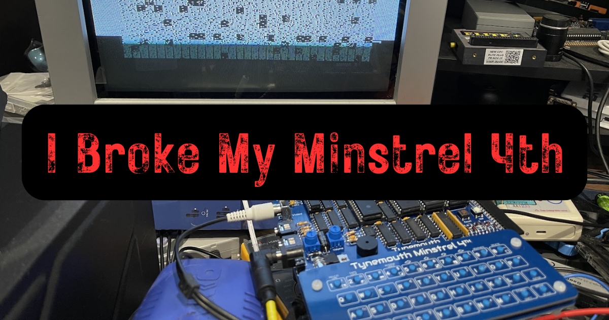
There is a particular kind of quiet in the moment you realise the problem you have spent all afternoon troubleshooting is all your own fault.
I bought the Minstrel 4th as a birthday present to myself. The plan was build it over a weekend, film it, write it up, post the “look what I made” pictures, move on to coding for the thing.
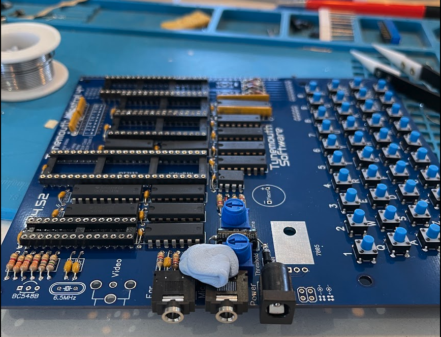
Instead, what actually happened, is that I rushed to meet my own self-imposed deadline, damaged it beyond my ability to solve, and had to ship the whole lot back to the man who invented it so he could repair the damage I had done.
Dave Curran of Tynemouth Software has already written the diagnosis up from his side, and it is a great read about how you troubleshoot these things. He was kind enough to call me “the owner” in his version. I was happy for him to name me, because IMO the lessons from this story are not in the repair, it is how a semi-competent builder talked himself into three separate unforced errors in one afternoon.
So here is my half of the tale, ugly parts included.

What the Minstrel 4th is
Dave’s Minstrel line of kit-computers recreates the early-era Sinclair machines on modern PCBs that you can actually build yourself. The Minstrel 4th runs ZX81, Jupiter Ace and Lambda 8300 ROMs, plus what was the crucial element for me, it also accepts RC2014 expansion cards. Rather than the awful ZX80/81 membrane it uses actual buttons. Which I mashed up on mine, but that’s getting ahead of myself.
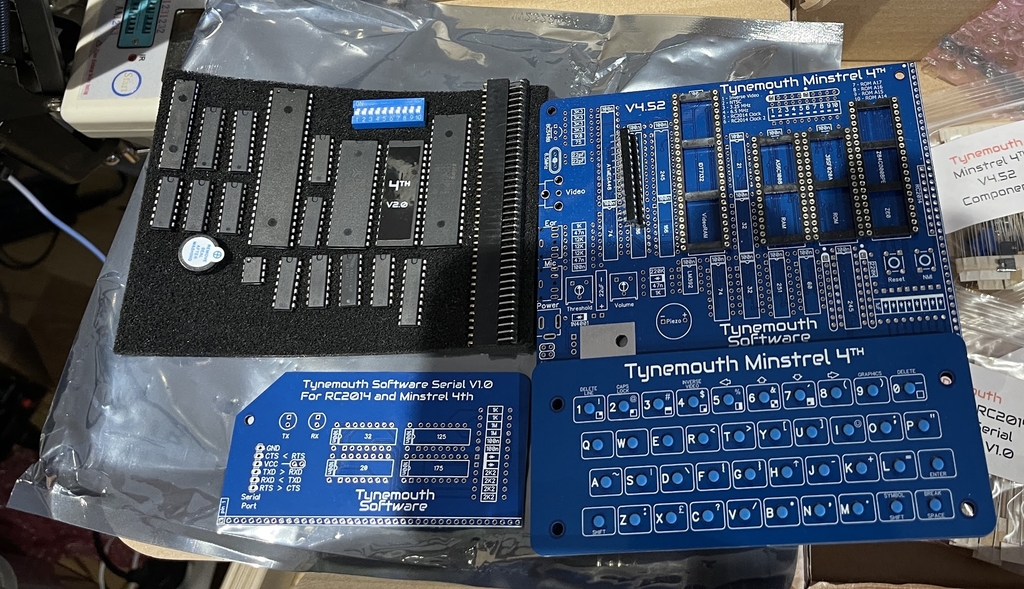
Contact Dave if you want to order a Minstrel 4th, but you can check out the Tindie listing here for all the specs and info.
I’ve never programmed in Forth so that is a side-quest for now. What intrigued me was I had a Minstrel 2 sitting unbuilt. This one would, in my imagination, tickle the “Z80 on a breadboard” itch in a more polished and robust way and scratch that Z80-as-a-microcontroller itch I had been putting off due to the sunk cost of my actual mostly-working RC2014.
A bit that is important for this story is how it creates the display output. There is no video chip. An ATmega microcontroller stands in for a CRTC (Cathode Ray Tube Controller). It counts up the address lines of the video RAM and generates the timing. Then a 74HC166 shift register turns bytes into pixels, much like the original machines did in the 1980s.
Seven parts in total are involved in just generating the display: the video RAM, the microcontroller and five 7-series logic chips. Remember that for later.
My Minstrel 4th came with the keyboard and the additional RC2014 software serial card, and when I put my order in I cheerfully told Dave I was happy to solder, minimal socketing thank you. Chris, you sweet summer child!
The build, and that deadline
Nothing about this kit was rushing me. The rush was all mine, and it came from planning around content that nobody, not one person, had asked for.
First, most immediately noticeable mistake, I soldered the keyboard switches in without using the labelled top plate as a guide, which ironically makes the job slower as well as messier. For my sins I got a row of wonky switches, and then made it worse by trying to straighten soldered switches with my fingers and burned a few with my soldering iron. Several of them are now, in Dave’s word, “mullered“.
I trimmed the component legs, as is tradition, but again in a mad rush. Cheap snips, poor light, tired ancient eyes, at reckless speed, working across the back of a board that has fragile traces running between the pads. I did not feel anything happen, there was no bang, no magic smoke.
First power-up
Power on, and … the screen was garbage.
Worth admitting here plainly because I skimmed it, read the manual and check the DIP switches before switching the thing on. I had none of them actually switched to ‘on’, and with none of them on there is no clock. Dave spotted that from my Bluesky post, even before I had got close to asking him.
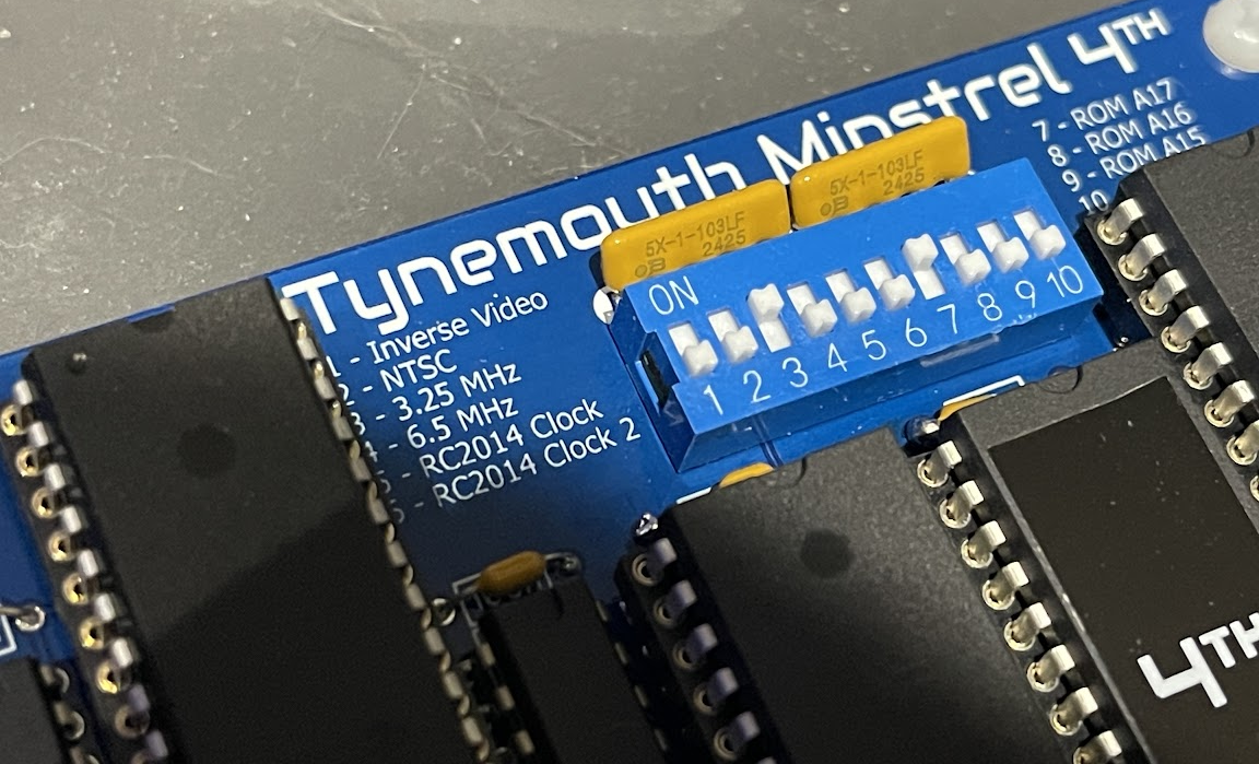
(Switches 1 and 3 for Jupiter Ace, 3 and 7 for ZX81)
Switches set, and it was still wrong. Corrupted characters, wrong text, blocks of the screen in the wrong place. Typing did not produce the expected characters, so I did what most people would do and started blaming the keyboard, which I had admittedly made a real mess of. That felt like the go-to suspect.
It was the wrong suspect, of course, and the way Dave proved it is informative.
Reading the fault off the screen
Dave had me switch to the Lambda 8300 ROM, because it beeps at power on and also beeps on every keypress. This gives you audible feedback from the machine when you cannot trust the screen. Lambda BASIC is not tokenised, so you type keywords out in full. He asked me to type the following, letter by letter:
10 PRINT 42
The screen showed:
00 OQIMS 42
Now, if the keyboard were faulty and the machine had received 00 OQIMS 42, it would have thrown a syntax error. It did not. It accepted the line and moved it up the screen, ready for the next one. Interesting.
Then RUN printed 42. So the Z80 side, the ROM, RAM and the keyboard I had accused were all clearly doing their jobs. The machine had the right thing in memory but was drawing the wrong things on screen.
That halved the possible culprits in one go. The next step is neater still. Look at what changed, in character codes rather than in letters:
| Typed | Shown | Code typed | Code shown |
|---|---|---|---|
| 1 | 0 | 1D | 1C |
| P | O | 35 | 34 |
| R | Q | 37 | 36 |
| N | M | 33 | 32 |
| T | S | 39 | 38 |
| 0 | 0 | 1C | 1C |
| 4 | 4 | 20 | 20 |
Every odd code came out as the even code below it. Characters that were already even came through untouched. That is bit 0 of the data going to the video RAM being stuck low, every single time, with no exceptions. The banner agreed, announcing itself as KAMACA 8200 instead of LAMBDA 8300.
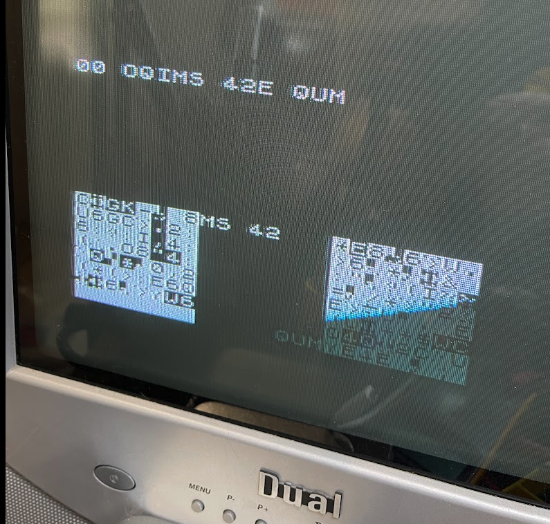
The mess at the bottom of the screen was a separate fault, but it reads the same way once you know the trick. On a 32 column display, 8 lines is 256 bytes, so gaps in blocks of 8 or 16 lines point at A8 or A9. Blocks 8 characters wide point at A3 being stuck high. Data bits garble your characters. Address bits move them around. The screen is telling you which one, if you can be bothered to work out the codes.
My own contribution at this point was to squint at the board with tired eyes and say “looks like I caught the board with my crappy snips, hope that is not the cause“. I then spent the next hour looking somewhere else.
Making it worse
While poking around randomly, I decided to reseat the ATmega chip. I levered it out (badly), bent a pin, bent it back, and the leg came clean off. Not even a nub was left to solder onto.
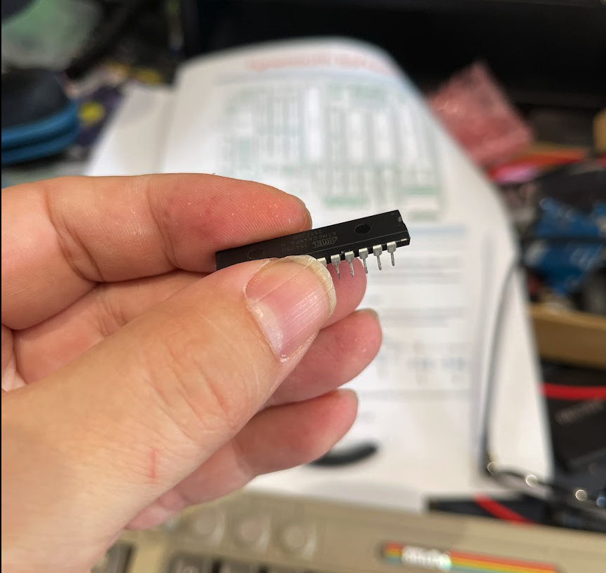
Naturally it wasn’t a chip I have a literal box full of. Oh no, the ATmega in question is discontinued.
I did not have a spare and Dave’s stock is finite and shrinking. A fixable board just became unfixable (without help), purely because I refused to slow down and do things methodically.
For the record, the pin I snapped was 28, the PAL/NTSC selection, which had nothing to do with my problem at all.
Board went in the post to Tynemouth and I clenched my teeth waiting for the verdict.
What was actually wrong
Dave sensibly put it under a USB microscope, which is what I should have done on day one. He found two nicks in the back of the board, both right next to capacitor legs. One had gone clean through a trace. The other was deep enough to be into the fibreglass and had taken out two.
Three broken traces:
D0, exactly as the character codes had said- The border signal, which is tied to the tape output, so it would have bitten me on the butt later when I tried to save files.
A9on the Z80 side, which explains the misplaced blocks
He confirmed the D0 theory before even touching the board, by writing a few lines of ZX81 BASIC in the EightyOne emulator that printed the startup banner, then modifying it to force bit 0 low. Out came KAMACA 8200, the same string my machine was showing. There is no bitwise AND in ZX81 BASIC, so it takes a divide by two, an INT to drop the fraction, and a multiply by two to get back.
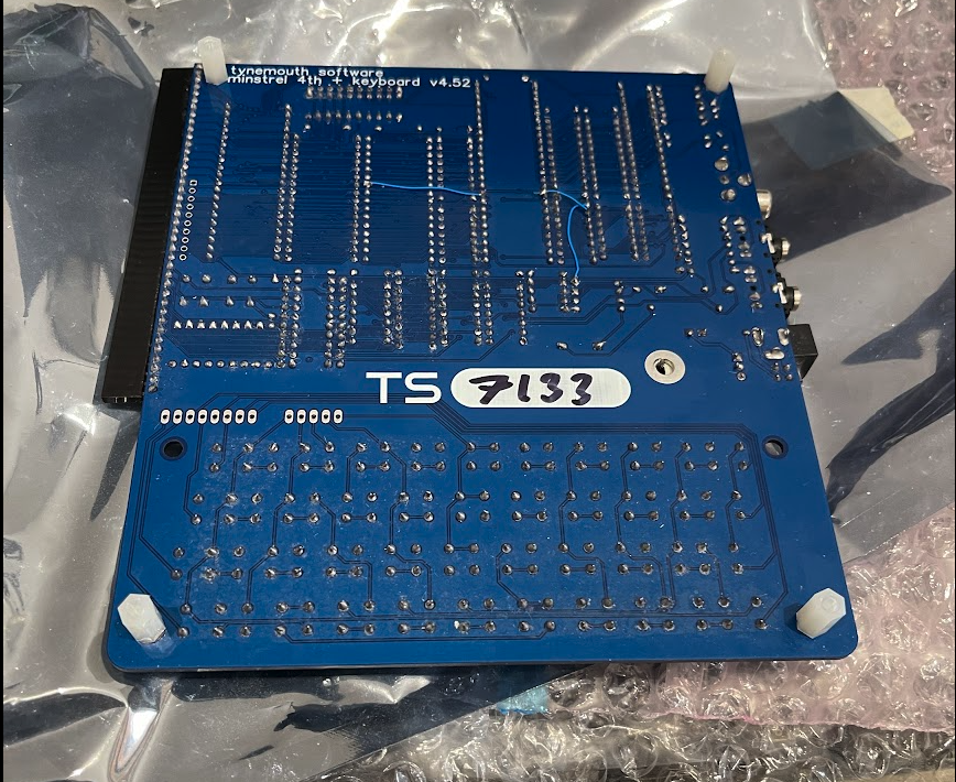
Three bodge wires soldered on the back of the PCB, and everything started to work!
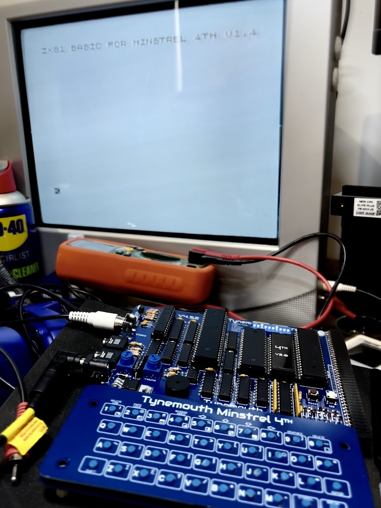
My board returned home on the thirteenth, and the only surprise waiting for me was that Dave warned me he left the power jumpers set his way rather than mine. There is a protection diode, so wrong jumpers means nothing would have happened rather than something expensive going up in smoke.
Total cost of my rushing: the price of a replacement microcontroller, postage both ways, a fairer-than-I-deserve repair fee, a fortnight lost, and a row of keyboard switches that still look ugly as all get out.
Lessons learned: Priceless.
What I would do differently
Before anyone gets all indignant on social media, yeah these lessons in hindsight are all obvious. That is rather the point. I taught most of them in the past but here I was breaking my own rules.
Do not build an unfamiliar kit to an invented deadline: The video was my idea. Building that weekend was my idea. Every one of my mistakes led from that decision, from moving fast on a job where speed buys you nothing but pain.
Trim leads properly and with the proper tools: Sharp, good quality flush cutters, blade parallel to the board, cutting away from neighbouring pads, once. Not cheap blunt snips stabbing around at the back of a densely routed board. Better still, trim the legs before you solder when the build allows it. Cheap snips open and close unevenly, and have a fat, rounded jaw that sits proud, so the cutting edge ends up nowhere close to where you are aiming.
Light and magnification are not optional past a certain age: I have not had an eye test in over five years. My eyes were crap when I did get an up to date prescription. Dave recommends illuminated magnifiers on anglepoise arms. I own a USB microscope and had I taken the time to dig it out and get it working I could have found the fault myself on day 1.
Use the kit as intended: The keyboard plate is a jig. Use it.
Read the manual before you diagnose: No clock because no DIP switches on is not a fault, it is a part of the book I did not read until after I had problems.
Read what the screen is telling you: The 10 PRINT 42 test, the character code comparison, the block sizes. That is a diagnostic method you can take away to any machine with memory-mapped video, for free.
Do not reseat innocent chips just to feel productive: If you have no evidence pointing at a chip, leave it.
Photograph as you go and ask for help early: Every productive move in this story came from posting photos and describing symptoms to someone who could help.
All credit where it is due
Thanks again to Dave Curran at Tynemouth Software who diagnosed this from photographs and my garbled descriptions, repaired damage I caused, and then asked politely whether he could write it up. His post is the technical half of this story and you should read it.
The Minstrel 4th itself was never the problem. It is a lovely kit, and it works really well. I have the Minstrel 2 and an RC2014 card still to build but with zero deadlines this time!
Slow is smooth, smooth is fast

That is a phrase I picked up from S.W.A.T. that I repeat to other people all the time, usually while they are hurrying something that will not go faster if they hurry.
My crappy attempt at building a Minstrel 4th cost me a fortnight, a discontinued microcontroller, postage in both directions, a repair fee and a bunch of uggo keyboard buttons, and every one of those because of the twenty minutes I thought I was shaving.
Take the extra hours. Enjoy it. Get good light on your work area, get the magnifier out, measure twice and cut the legs once. Read the book before you start and check your work before you power it up. You will be finished quicker, and with a machine that boots first time!
 AndyH/Hewco Retro Game Developer Interview